|
   |
|
Page 3 |
Newsletter 128 Spring 2020 © Hampshire Mills Group |
|
Sherborne Mill is now generating!
Harry
Clarke
Photos by Keith Andrews
|
|
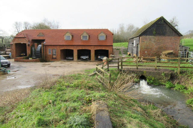
As a
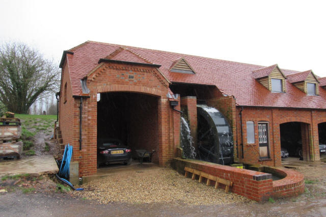
recap, our aim here on the historic site of
Sherborne Mill has been to establish a
power-generating waterwheel and incorporate it
within a building that is sympathetic to the
setting.
We
have taken the construction slowly.
All
necessary foundation work and retaining walls and
wheel pit were built from April to December 2018. |
 |
|
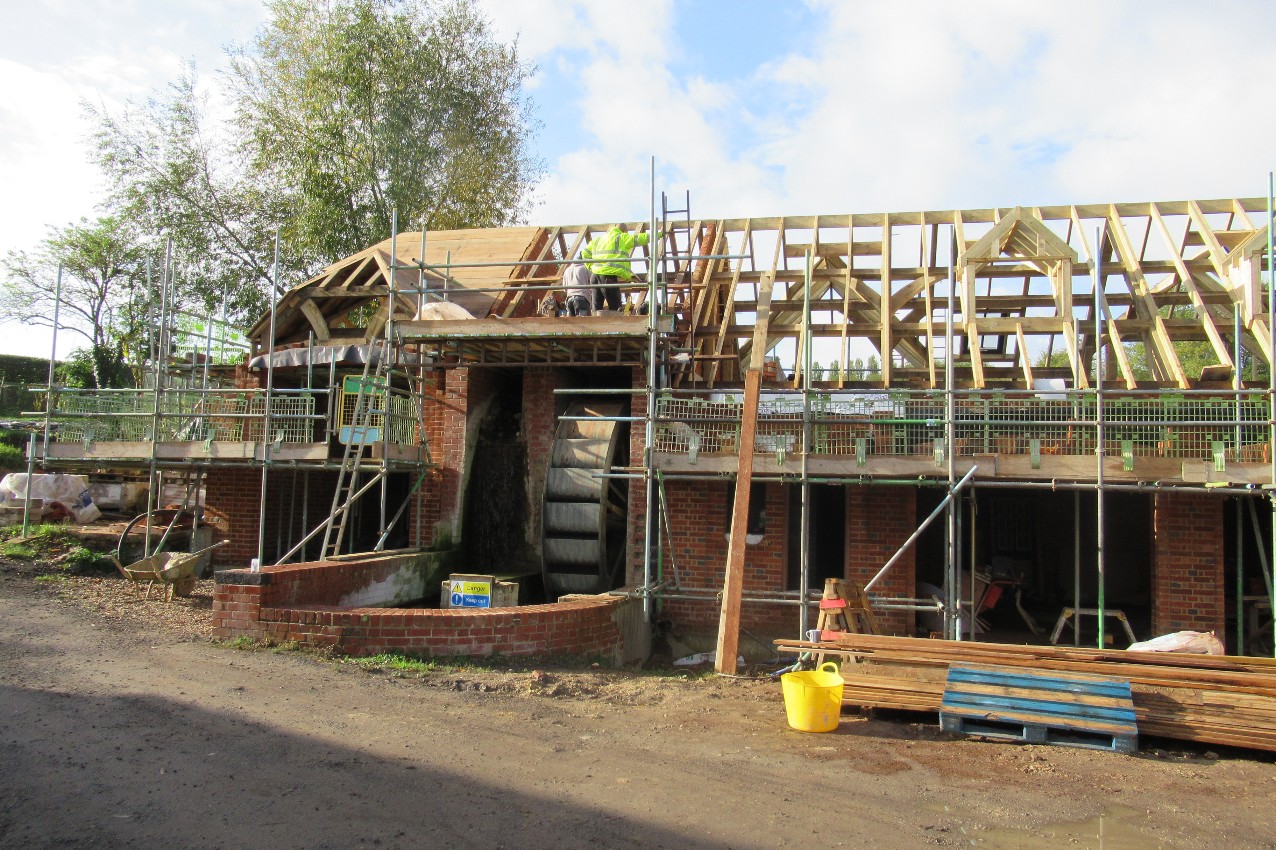
The
main brickwork, roof framing, and tiling took place
between the same months of 2019. Today, the
building stands as a dry shell and is to be fitted
out during 2020. In order to catch the last of the
Government’s Feed-in-Tariff programme the wheel was
necessarily installed as soon as the foundations
would allow. |
 |
|
It produced
electricity to the grid from 10 December 2018
securing its accreditation with ten days to spare
before the 31 March 2019 deadline. This usefully
secured us a feed-in rate of 8.26p per kWH (for the
next 20 years on a deemed 75% feed-in proportion of
our maximum rated capacity of 3.41kW).
With
accreditation secured we then halted the wheel and
lowered the mill head during the summer just gone to
allow the construction of the building to take place
around it in safety. Although we had run the wheel
for three months during 2019 the top ‘soldier’ brick
course of the repaired leat walls had not been in
place. This meant we had not been able to bring the
water level in the mill head right up to full
working height. This reduced flow meant that the
maximum power we had seen in 2019 from the wheel was
about 2.2kW. Clearly there was more to come.
Syrupy
stuff
Over the
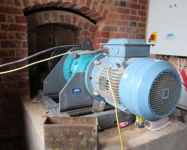
New Year I therefore re-installed the electric
synchronisation box (a HGP2 system supplied by
Sustainable Control Systems) which had been kept
away from the dusty site. I also serviced the wheel
by re-greasing the taper roller bearings seated
within the two plummer blocks in which the axle
turns. Finally, I changed the oil in the double
epicyclic speed multiplier gearbox – 3 litres of
fully synthetic EP220 with much the consistency of
golden syrup.
Exciting times
On 2
January I gave it a go. The trick to getting the
wheel to synchronise to the National Grid is one
that my partner Devika and I are getting good at.
Essentially, the wheel starts from rest with the
stop-logs controlling water from the leat all in
place. We slowly begin to start cracking open the
water flow – usually by sticking a garden fork under
the stop logs and levering them up. |
|
Obviously the wheel starts to turn and with it the
generator. There is however quite a lag in the
process. In fact it takes about 45 seconds between
adjusting the logs and the wheel settling down to a
revised speed based on the adjusted flow. Once the
wheel starts to turn at about 5rpm the theory is
that the self-excited generator starts producing a
voltage. (As some will know, self-exciting
generators rely on the iron cores on which the field
windings are wound retaining some magnetism from the
last time of operation). When starting from rest,
and so electrically dead, this residual magnetism
nonetheless primes the creation of an initial
voltage which then drives further electromagnetism
via the field windings, and off it goes.
|
 |
|
Anyway, we duly did this but got nothing. After much
head-scratching, reading of manuals, and phone calls
it became clear that we had to ‘re-flash’ the
generator. This is required with any self-exciting
generator that has been stationary too long and from
which the residual magnetism has ebbed away. The
process is pretty much as it sounds. Mains voltage
is applied directly to the field windings, which,
being made of thick copper, offer very little
resistance. The instant current draw is huge making
the eponymous flash and blowing apart any fuses
unwise enough to be in the way. Quietly, without
mentioning it to the family and armed with insulated
pliers, welding gloves, and a mask, I set to. The
results were threefold:
•
Devika came rushing out wondering what had happened,
all the household lights having dimmed;
• the 40amp generator trip popped;
• it worked!
Slightly tediously however the next day my laptop on
which I am writing this, and which had been charging
at the time in the house, wouldn’t boot up. It
subsequently required a £500 new motherboard. Yet
another expensive mill owning lesson learnt!
Synchronised spinning
Anyway, the next day, with the generator freshly
re-magnetised we again slowly fed water to the
wheel. Duly, at around 5rpm, the control box first
began to register a rising voltage. The working
speed of the wheel is a constant 8rpm – at which
point the geared generator is rotating at exactly
1500rpm and producing a 50Hz sine wave. This is of
course exactly the same shape and frequency as that
produced by the National Grid.
By
increasing the wheel speed slowly the voltage rises
further. Once it gets to 160V (the wheel speed being
about 7.6rpm at this point) the control box display
also starts, showing the frequency of the output
sine wave. Typically it will begin at around 47.0Hz.
The trick, at this point, is to cautiously and
incrementally crack open the stop logs further so
that the speed creeps up very slowly until the wheel
is running at a speed which means the generator is
producing as near as dammit 50Hz. At this point the
clever electronics and fairly hefty capacitors in
the control box somehow manage to buffer the two
almost synchronous but inevitably out of phase sine
waves (the one from our National Grid connection and
the output from the wheel) so that they fall into
both phase and frequency then with a big ‘kerchunk’
of a monster relay and shudder from the wheel, the
two are connected.
|
|
This
was duly achieved. From this point, all need to be
gentle with the stop logs evaporates. We simply
remove them all, giving the water in the mill head
an unobstructed path down the leat to the wheel.
More water does NOT however make it go any faster.
The National Grid has effectively got a grip on the
wheel at this point and will not allow the
generator, to which it is geared, to rotate at
anything other than the speed which precisely
supports a 50Hz sine wave. More water does however
create more torque on the axle, more current and
hence more power.
|
 |
|
Satisfied
with this, with the mill head up to working height
for the first time ever and a steady 2.68kW showing
on the output meter, we left the whole lot running
nicely.
|
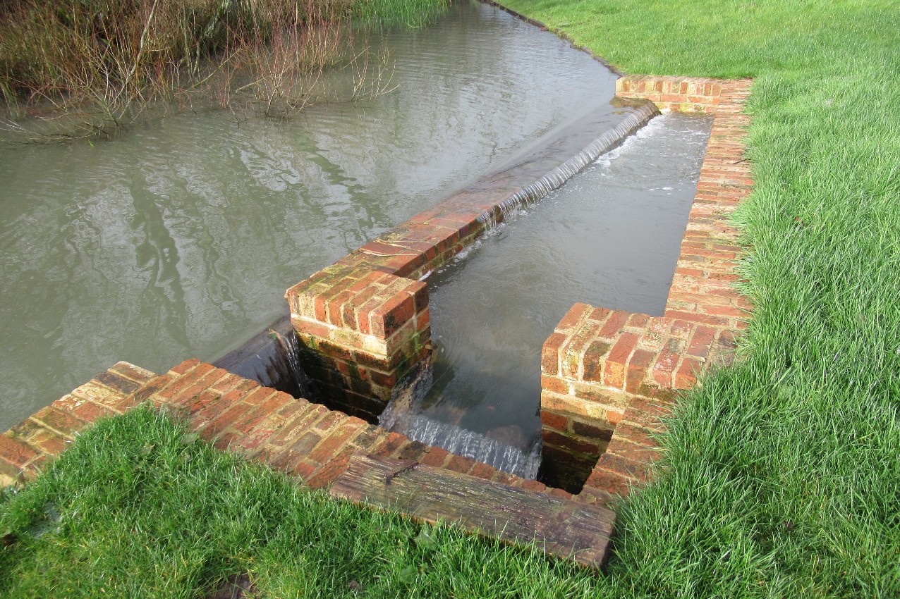
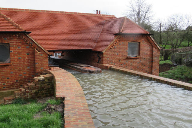
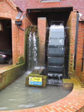
The spillway in the mill pond regulates the water
flow with a clever sloping cill.
The excess water runs off into the bypass channel,
which can be seen on the right of the picture at the
start of the article.
|
|
Ripping
yarns
That
night I awoke. Despite the gentle noise of the rain
it was clear that something else louder was going
wrong. Jumping up and to the window – our bedroom
faces the wheel across a courtyard – I could see the
wheel spinning fairly wildly and obviously without
any restraining load. Having rushed about semi-naked
outside in the dark for a while, pulling stop-logs
from the control sluice and putting others back in
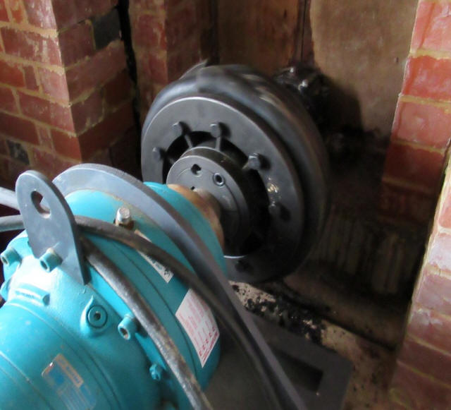
the leat, I went into the generator room. Although
the wheel is coupled to the gearbox, and hence the
generator, it is not done rigidly. Between the wheel
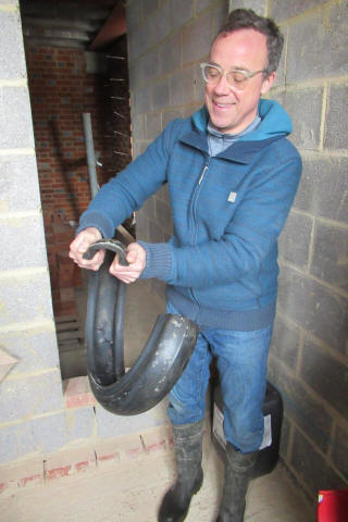
and the gearbox is a ‘Fennerflex 140’ coupling which
looks much like a wheelbarrow tyre.
|
|
One
bead is gripped by a flange on the waterwheel shaft
and the other by a flange on the gearbox input
shaft. As a result, drive and torque is transmitted
through the fabric-reinforced rubber of what would
be the circumferential tread of the ‘tyre’.
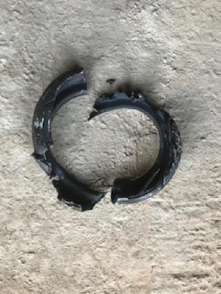
Anyway, the F140 had proved unequal to the task;
despite being capable of handling 3kNm of constant
torque and a 5kNm starting load, it had been ripped
to literal shreds (see right) by the power increase
caused by the overnight rain. |
 |
|
Stormy
shakedown
Assuming it was bad luck, I ordered another rubber
replacement. Later that day though, dusting off my
torque tables, it became clear that our wheel, under
load, was more than capable of exceeding 3kNm and in
fact would probably operate around a constant 4.7kNm
when the buckets were fully loaded with water.
Having ordered a new F140 tyre I fitted it, as a
stopgap and at reduced power, only to find that it
lasted less than 72 hours. The full solution – an
F180 coupling (which is substantially bigger and of
course another expensive mill-owning lesson) was
inevitable. This was fitted on 20 January and
whilst the thick rubber is looking a little strained
when under full load, in the time since it is
bearing up well. Maximum registered load on the
control box with this configuration has been 3.31kW
which, as you would hope, is pretty much the same as
the maximum rated capacity of 3.41kW which shows
that all is well. With Storm Ciara having deluged
our catchment and Dennis now on the way it’s
certainly getting a good shakedown.
The Generation Game
Although it might seem a bit wasteful not to have
had the wheel running during the summer of 2019, I
am quite pleased we didn’t. Despite SSE, our energy
supplier, assuring me that our Economy7 meter would
be fine to cope with measuring the generated power –
it wasn’t. It didn’t just fail to shut down the
registers when we were feeding power back to the
grid; worse still, it actually counted the exported
power twice! Once as it went through the day-time
register and again as it somehow flowed backwards
through the night-time register. We are currently
in dispute for about £600 (expensive lesson number
3) but we may get somewhere I hope.
This
year though I have been keeping a close note of the
wheel’s generating performance and it’s looking
good. Taking the period in which the wheel was
working continuously from 20 January when the F180
coupling was fitted to today (13 February) we have,
on average, generated 58.8kWh every day and had to
pay for only 1.8kWh (which is effectively only those
odd times when our generation level is exceeded by
the demands of the house). I suspect we are
exporting about half of our generated power which,
whilst good for society, seems a bit of a needless
loss whilst we are still paying handsomely for
petrol. Watch this space!
|
 |
 |
|
|
